| |
|
|
|
Media Information
Press Contact
Michelle Moody
Moody & Associates
+1-214-363-3460
|
|
|
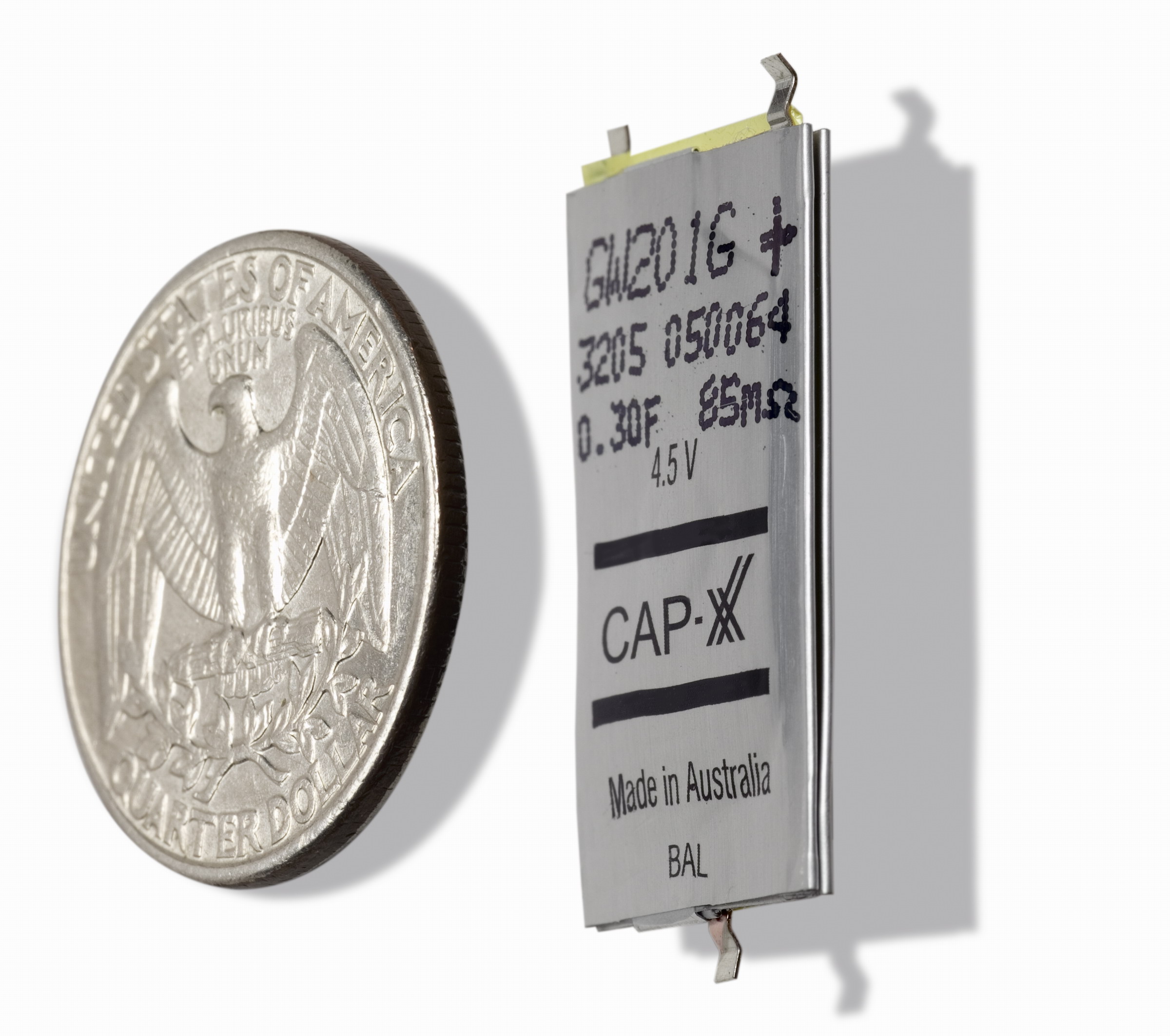
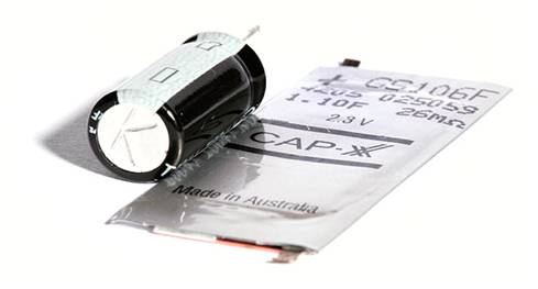
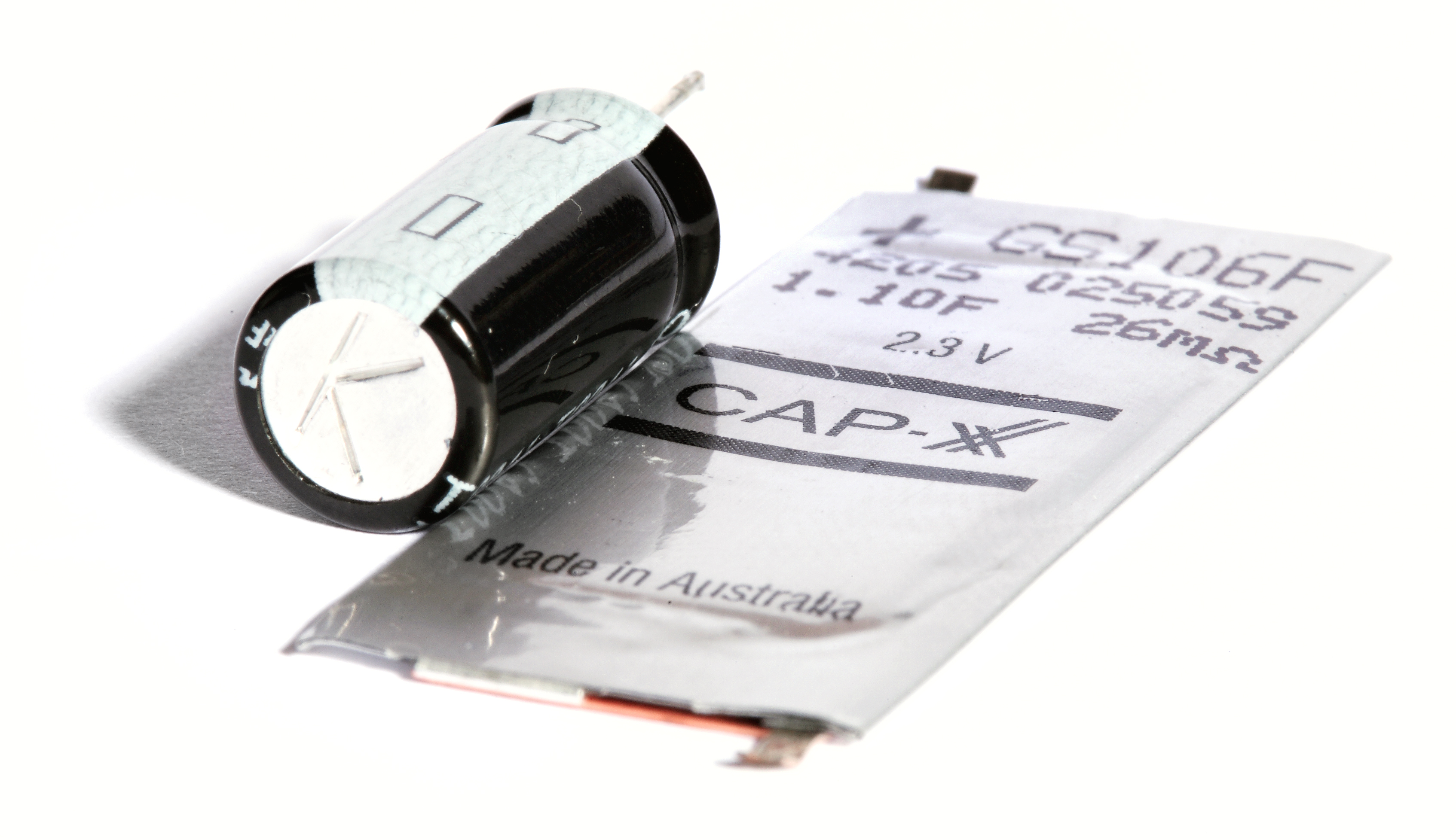
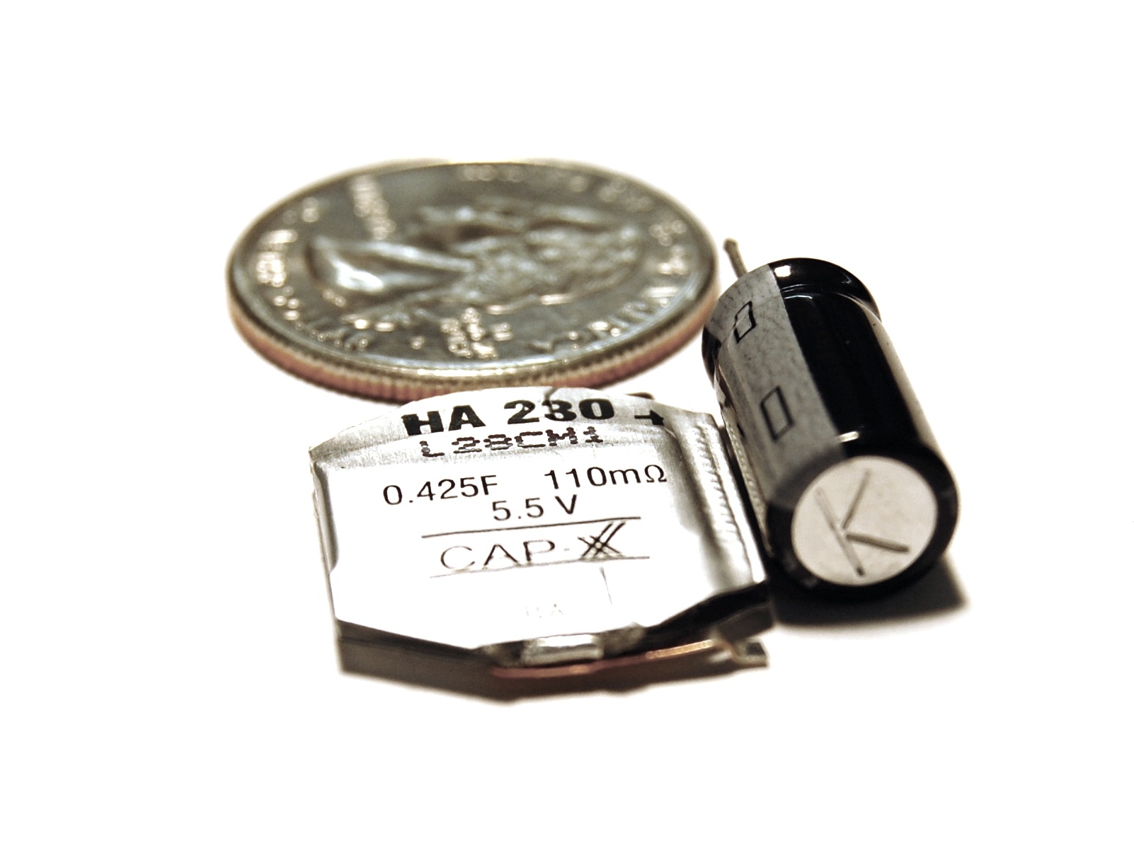
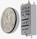
CAP-XX Photo Gallery
Pictured here with a US quarter dollar, CAP-XX
supercapacitors benefit from a unique nanotechnology construction, which packs the highest energy and
power-densities available today into thin, lightweight, prismatic packages (as little as 1mm thick). These
ultra-slim supercapacitors provide the peak power required for high brightness LED flash (BriteFlash),
enhanced audio reproduction (BriteSound) and many other applications (BritePower). |
High Res |
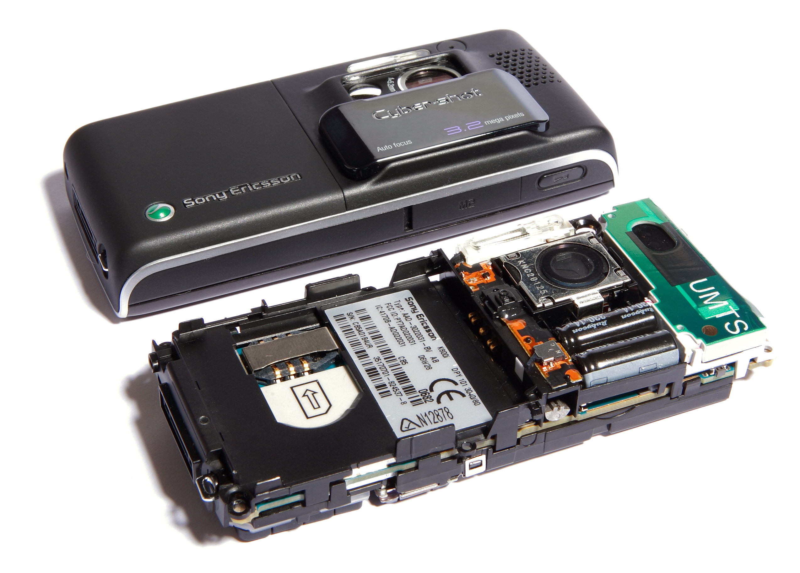
The key advantage of LED Flash over Xenon in camera
phones is size. An electrolytic capacitor is required for Xenon Flash and a slim supercapacitor powers an
LED Flash. For instance, a SonyEricsson K800 uses two electrolytic capacitors each measuring 7mm dia. x
18mm long. The CAP-XX LED BriteFlash™ solution uses two supercapacitors measuring
17mm x 39mm x 1.1mm side by side to keep the solution very thin |
High Res |
|
BritePower™ Solutions/Devices Using Supercapacitors
|
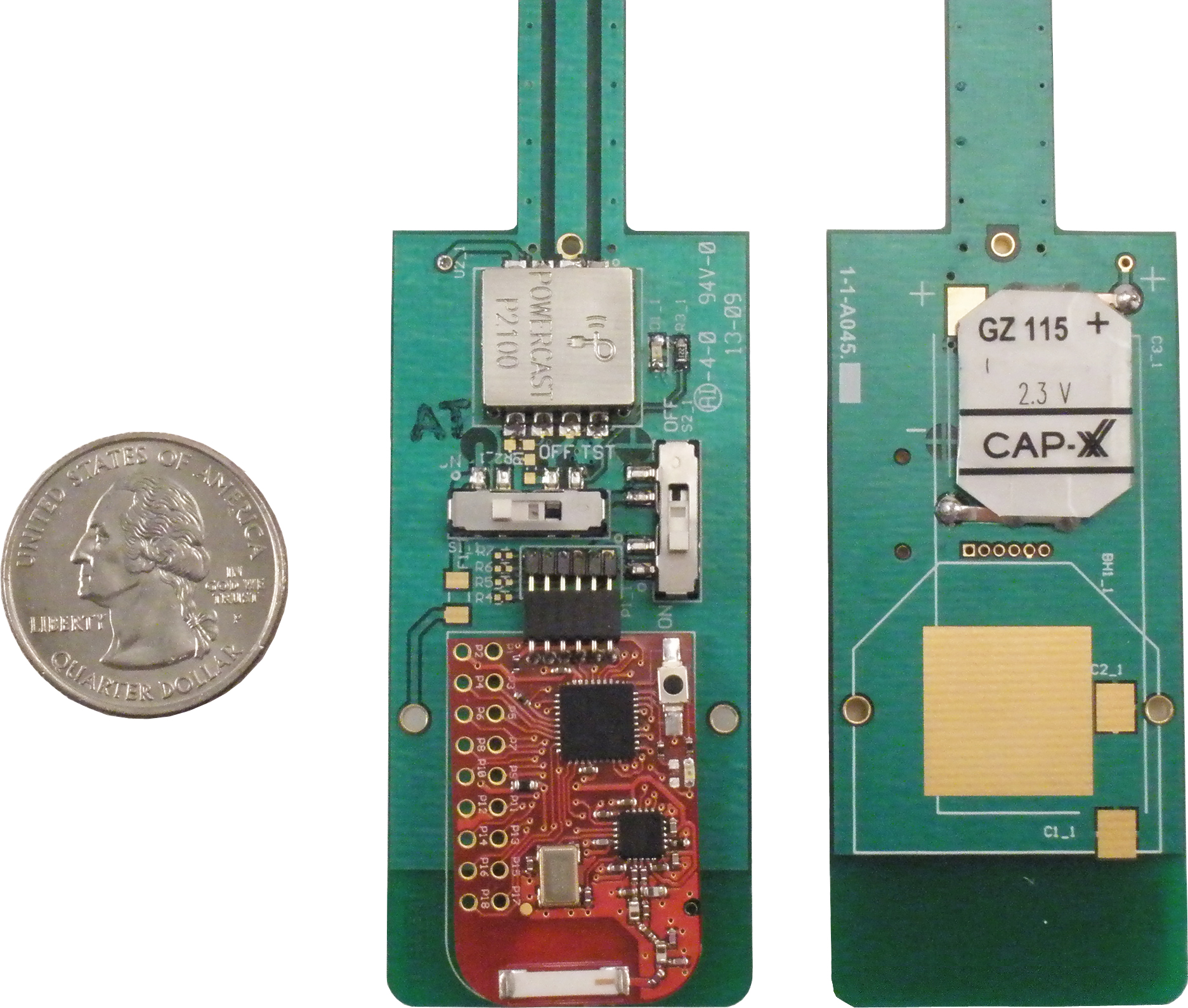
| Powercast RF Energy Harvesting Module |
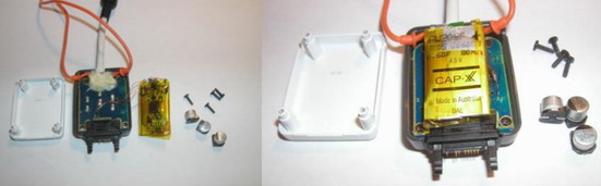
This wireless power module combines Powercast's
RF energy-harvesting technology with a CAP-XX supercapacitor to create a perpetual,
battery-free power source for the wireless sensors commonly used in security, environmental
and condition-monitoring systems. The module integrates a power receiving antenna, a
Powercast Powerharvester to convert the radio waves into low DC power and a CAP-XX
supercapacitor. The supercapacitor stores the harvested energy and provides peak
transmission power to a wireless sensor/transmitter board such as the Texas Instruments
eZ430-RF2500T. The complete module measures 8" tall x 1" wide x ¼ thick.
Contact Powercast at
www.powercastco.com for more information. |
Front and Back Close-up of Components
High Res |
|
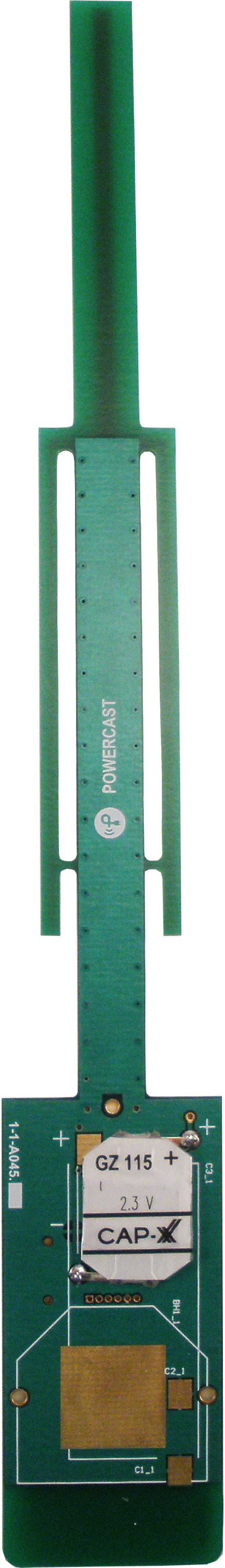
Complete Module Including
Power
Receiving Antenna
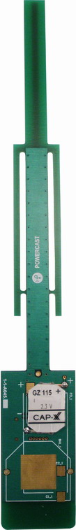
High Res |
Perpetuum Vibration Energy Harvesting
Module
Perpetuum's PMG17 vibration energy-harvesting
micro-generator, together with a CAP-XX supercapacitor, allow wireless sensor system
manufacturers to design battery-free condition monitoring systems that collect and report data
on machinery for improved asset management. The PMG17 microgenerator converts unused
mechanical vibration into a low but steady source of electrical energy. The supercapacitor then
stores the energy and delivers the peak power needed to transmit sensor condition data over
wireless networks such as IEEE 802.15.4 (Zigbee) and 802.11 (WLAN). Together they can power
wireless sensor nodes indefinitely. Contact Perpetuum at
www.perpetuum.co.uk for more information. |
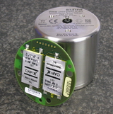
High Res |
|
| High-Power LED BriteFlash™ vs Xenon:
Camera Phone Flash Comparison |
Overview: This provides visuals from a 2009
study updating the company's 2006 study. Tests again showed that the LED BriteFlash approach
delivers more light energy than most xenon flashes in a thin form factor suitable for slim camera
phones and digital cameras. For more details and conclusions, see the press release:
http://www.cap-xx.com/news/FlashComparison.htm. |
The two photographs of the girl were taken in low light
from 2 meters distance to compare a small xenon flash in a current camera phone and the
supercapacitor-powered LED BriteFlash™ solution:
- Left: LG KU990 5-megapixel phone with a xenon flash unit delivers flash power so low
that the girl is barely visible as a silhouette.
- Right: Nokia N73 modified with CAP-XX BriteFlash solution - supercapacitor powers 3
LEDs at 1A each for a total flash power of 12W.
|
|
|
The two photographs of the colour scene with
metronome were taken in a dark room from 2 meters distance to compare a standard
battery-powered LED flash in a current camera phone and BriteFlash:
- Left: Nokia N96 with 2 LEDs but no supercapacitor support. Note the poor colour
reproduction from the colour chart. There is also a metronome ticking at 1Hz to show blur due to
exposure time 1/10s.
- Right: Nokia N73 modified with CAP-XX BriteFlash solution - supercapacitor powers 3
LEDs at 1A each for a total flash power of 12W. The colour chart shows much better colour rendition
and the metronome arm shows less blur from a faster exposure of 1/15s.
|
|
|
Light Power and Light Energy
Measurements: The key to clear pictures is Light Energy - the total amount of light that fills a
camera's pixels during image-capture time. On the other hand, Light Power refers to the intensity of
a flash. To calculate Light Energy: Light Power (Lux) x Flash Exposure Time (Secs) = Light Energy
(Lux.Secs).
- The Xenon flash has excellent light power, but a very short flash exposure time.
- An LED flash, powered by a supercapacitor, delivers lower light power over a longer
flash exposure time for total Light Energy that exceeds most Xenon flashes.
|
| Comparison of Light Energy between Xenon, BriteFlash and
Low-Power LED Flash |
| Source |
Storage
Capacitor |
Distance
(m) |
Peak Light
Power (lux) |
Exposure
Time
(msecs) |
Light
Energy
(lux.secs) |
Xenon
Samsung G800 |
Unknown |
1 |
303,000 |
<1 |
11.5 |
Xenon
SonyEricsson K800 |
2x 14µF |
1 |
217,000 |
<1 |
15.8 |
Xenon
Nokia N82 |
20µF |
1 |
161,000 |
<1 |
10.2 |
Xenon
LG KU990 (Viewty) |
10µF |
1 |
52,000 |
<1 |
2.6 |
BriteFlash
2x LEDs @ 2A each |
0.55F |
1 |
425 |
17 |
6.0 |
| 33 |
11.2 |
| 67 |
21.7 |
Medium power LED Flash
1x LED @ 1A |
0.55F |
1 |
135 |
67 |
8.9 |
Low power LED flash
2x LEDs, Nokia N96 |
NA |
1 |
30 |
67 |
2.15 |
| 100 |
3.45 |
Low power LED Flash
1x LED, Nokia N73 |
NA |
1 |
20 |
90 |
1.71 |
| |
|
|
|
|
|
Xenon
Samsung G800 |
Unknown |
2 |
72,000 |
<1 |
2.90 |
Xenon
SonyEricsson K800 |
2x 14µF |
2 |
57,000 |
<1 |
4.45 |
Xenon
Nokia N82 |
20µF |
2 |
40,000 |
<1 |
2.45 |
Xenon
LG KU990 (Viewty) |
10µF |
2 |
15,000 |
<1 |
0.72 |
BriteFlash
2x LEDs @ 2A each |
0.55F |
2 |
130 |
17 |
1.9 |
| 33 |
3.6 |
| 67 |
7.0 |
Low power LED flash
2x LEDs, Nokia N96 |
NA |
2 |
8.2 |
67 |
0.55 |
| 100 |
0.86 |
Low power LED Flash
1x LED, Nokia N73 |
NA |
2 |
5.0 |
90 |
0.43 |
| |
|
|
|
Flash Solutions Tested:
- Xenon: SonyEricsson K800, LG KU990, Nokia N82 and Samsung G800 all with 5-megapixel
cameras but with varying size electrolytic storage capacitors.
- Standard battery-powered LEDs: Nokia N73 (3.2-megapixel) and N96 (5-megapixel).
- Supercapacitor-powered LEDs: To demonstrate the BriteFlash approach, CAP-XX used a small,
thin (20mm x 18mm x 3.8mm thick), dual-cell supercapacitor to drive a two-LED array of Philips
LUXEON® PWM4s at 2A each or 4A total during the flash pulse.
|
Comparison of Solution Size and Energy
Density
The key advantage of LED Flash over Xenon in camera phones is size. The image on the
right compares the electrolytic capacitor used in the SonyEricsson K800 and the supercapacitor used for
the LED Flash. The SonyEricsson K800 uses two of these electrolytic capacitors each measuring 7mm
dia. x 18mm long. Similarly, the LED Flash solution uses two of these supercapacitors measuring 17mm x
39mm x 1.1mm side by side to keep the solution very thin. |
|
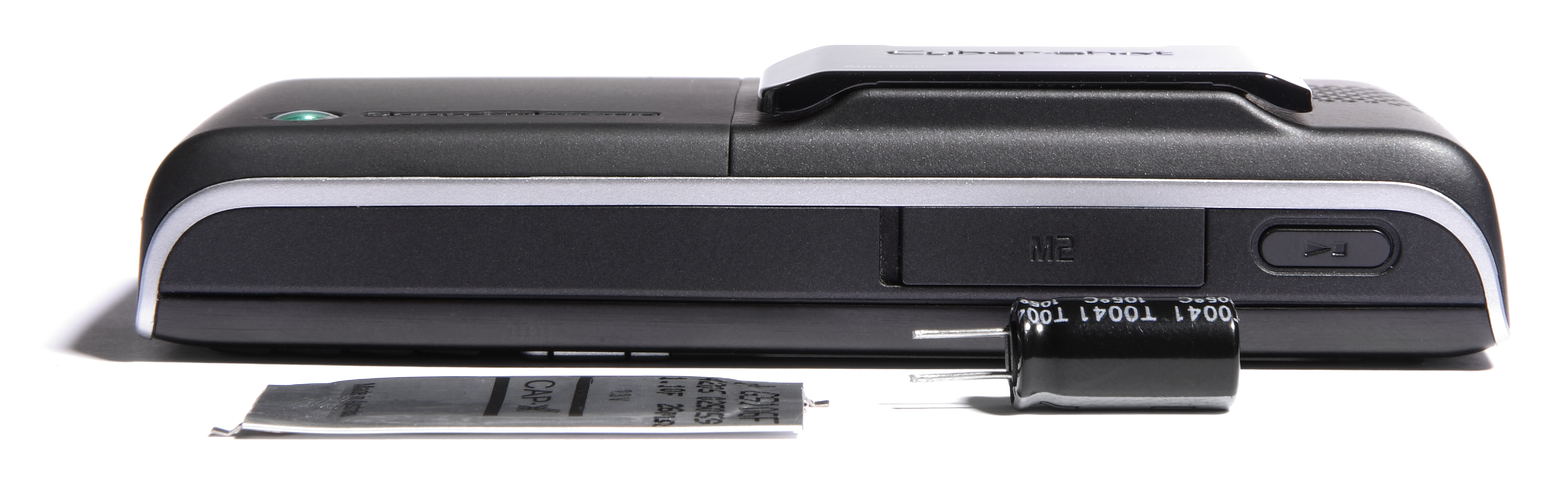
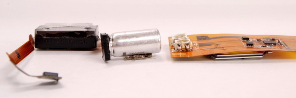
The bulky electrolytic capacitor
precludes a thin form factor for a Xenon flash solution with adequate
light energy.
Pictured is the SonyEricsson K800. The internal shot shows two electrolytics fitted inside and the
other shows the electrolytic and supercapacitor in profile next to the phone. |
|
|
|
|
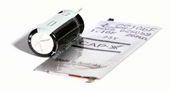
Size comparison between prismatic
supercapacitor and cylindrical electrolytic storage capacitor used for xenon flash. The SonyEricsson
K800 uses two of these electrolytics; the Nokia N82 uses one of the same size.
|
Xenon
|
Supercapacitor-enabled
LED flash (BriteFlash)
|
Bulky:
- Large electrolytic storage capacitor
- Total volume of xenon solution in SonyEricsson K800 ~3.8cc and 7mm thick |
Small and thin:
- Prismatic supercapacitor
and LEDs
- Typically < 2cc and 2 - 4mm thick 1 |
Fragile (Drop test):
- Xenon tube
- Electrolytic connection to flex PCB prone to fracture due to large mass of capacitors
and flimsiness of PCB |
Rugged (no difficulties with drop test):
- No large mass
- No fragile parts |
Safety:
1.5J of energy stored at 330V can
give a nasty shock, particularly near the ear |
Safe:
Low voltage, no safety issues |
| High Voltage (HV) trigger circuit needed for xenon
flash tube, > 4000V. Special measures and/or clearance is required to prevent arcing to other
circuits |
No HV, no special steps to prevent arcing to other
circuits |
| Mechanical shutter required to prevent
overexposure: extra cost, size & power |
Works with a rolling shutter. No mechanical shutter
required |
| High voltage and current pulse for xenon strobe
causes Electro Magnetic Interference (EMI) |
High current delivered from supercap,
EMI easier to manage |
| Still need a separate LED for video/torch mode |
Same LEDs used for flash and video/torch |
| Long time to re-charge electrolytic capacitor between
photos (~8s for SonyEricsson K800) |
Short time to re-charge supercapacitor
between photos (~2s) |
| Electrolytic capacitor cannot be used for any other
peak-power needs |
Supercapacitor can be used to meet all peak power needs
in the cell phone including:
- Flash pulse
- GPS readings
-
RF Transmission for GPRS
- Audio |
Very high-powered light delivered in >
200µsec:
- No photo blur
- Can take an action shots in low light |
Light energy delivered over longer time:
-
Capable of high-quality still shots, but cannot take action shot in low light
-
Image stabilization software can correct for hand movement |
| High Res JPG Version |
| 1Thickness will depend on implementation: two
single-cell supercapacitors side by side (double the footprint and half the thickness), or a dual-cell
supercapacitor with the two cells stacked on top of each other (half the footprint and double the
thickness) |
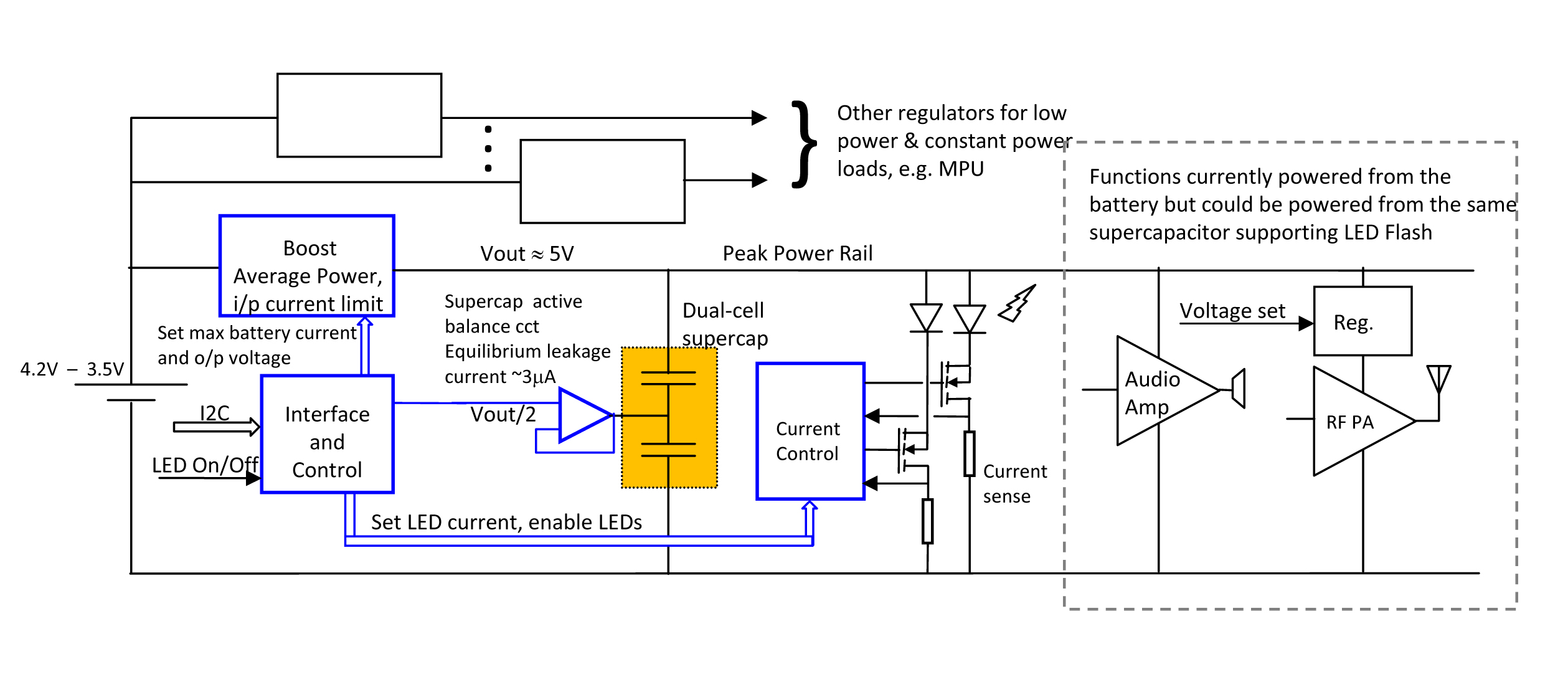
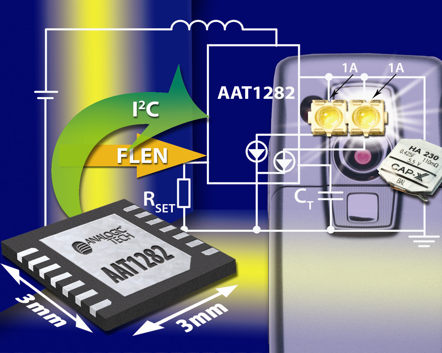
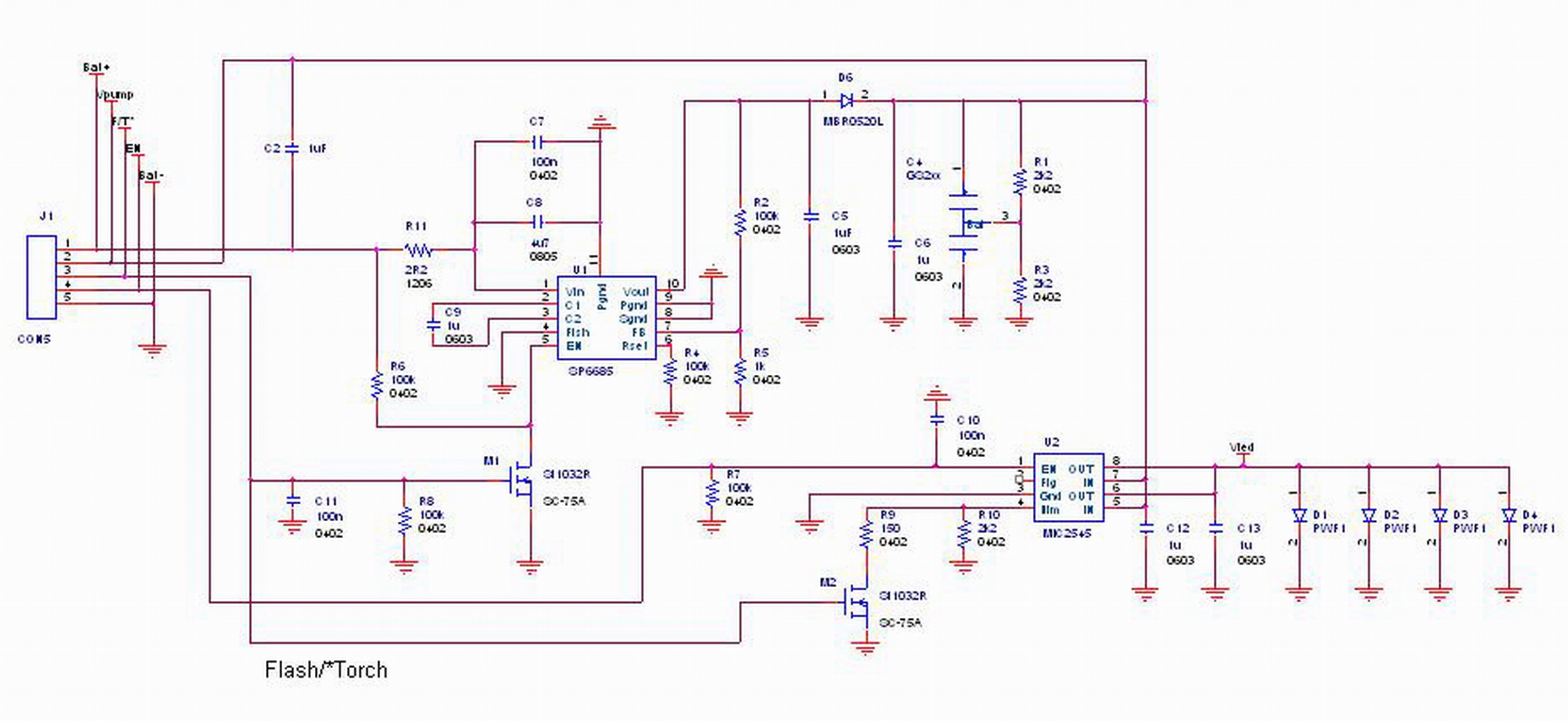
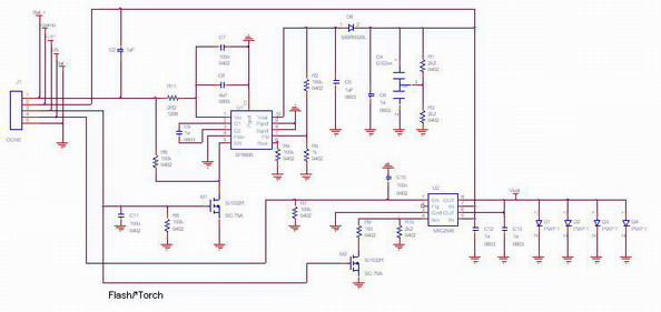
To achieve high LED power, designers can add a thin
supercapacitor to deliver peak flash-power, using the battery to cover average power needs
and recharge the supercapacitor between flashes. Integrating the circuitry outlined in blue (boost
converter, supercapacitor balancing, I2C interface and LED current control), new
supercapacitor-optimized LED flash drivers from major IC companies such as AnalogicTech and ON
Semiconductor are now available to save time, board space and component cost. A white paper
explains
more at
http://www.cap-xx.com/resources/pres_wp/pres_wp.htm#wp.
|
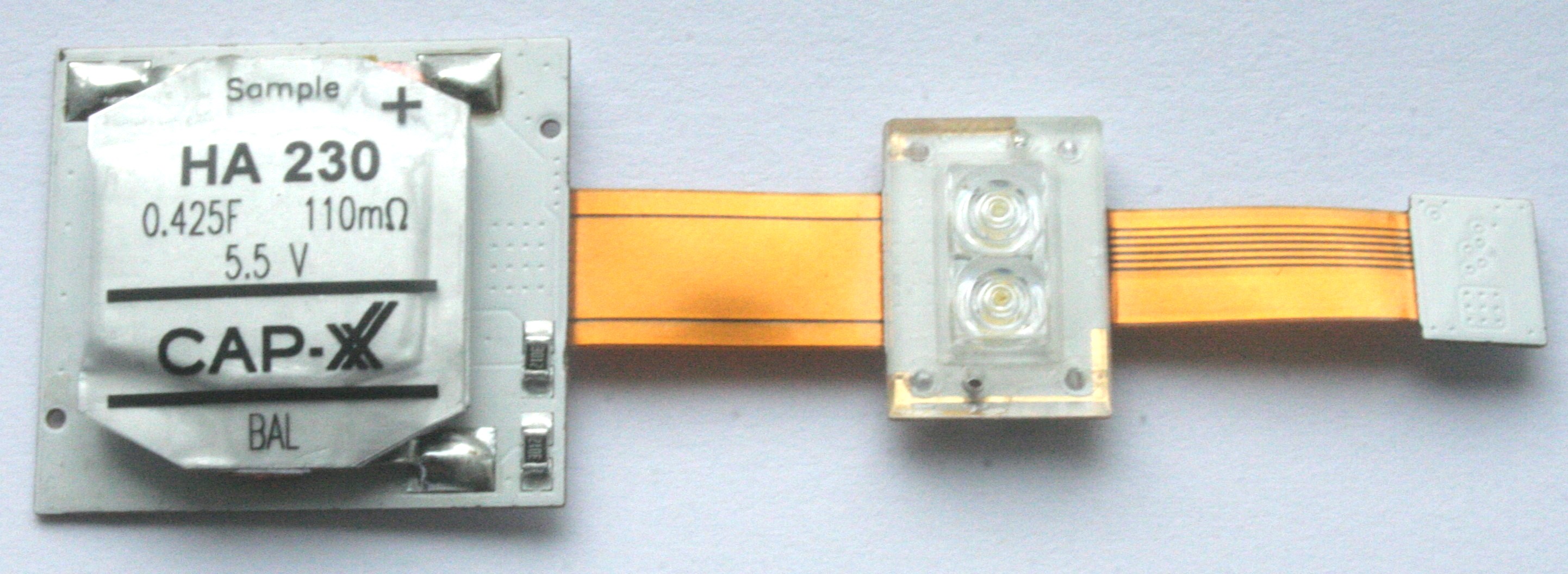
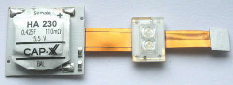
Supercapacitor-enabled LED
Flash Modules |
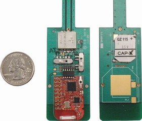
This supercapacitor-powered LED flash module reference design (pictured below), developed
by Seoul Semiconductor, uses a thin, prismatic HA230 CAP-XX supercapacitor and an
AnalogicTech AAT1282 LED flash driver (on reverse side) to drive high-current Seoul Semiconductor
LEDs. To discuss this module with Seoul Semiconductor, contact Jesper Bennike,
Technical Sales and Solution Manager
Mobile: +45 22951550
Office: +45 38887550
Jesper@Seoulsemicon.com
|
 |
|
High Res |
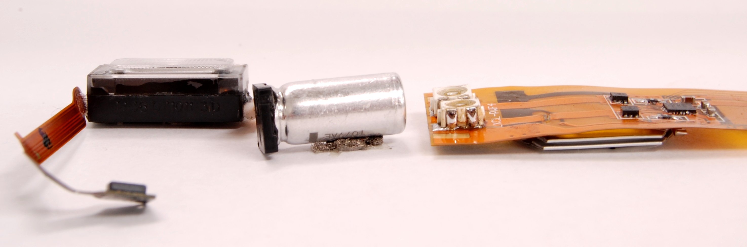
The supercapacitor-powered LED flash
module reference design (pictured below right), developed by ON Semiconductor, uses a thin
CAP-XX HA230 supercapacitor (on the underside) and the ON Semiconductor NCP5680 flash
driver to drive high-current Lumileds LEDs. Also pictured (left) for comparison is the Nokia N82
xenon flash solution with its large, cylindrical electrolytic capacitor.
|
 |
|
High Res |
|
BriteFlash™ in Action
|
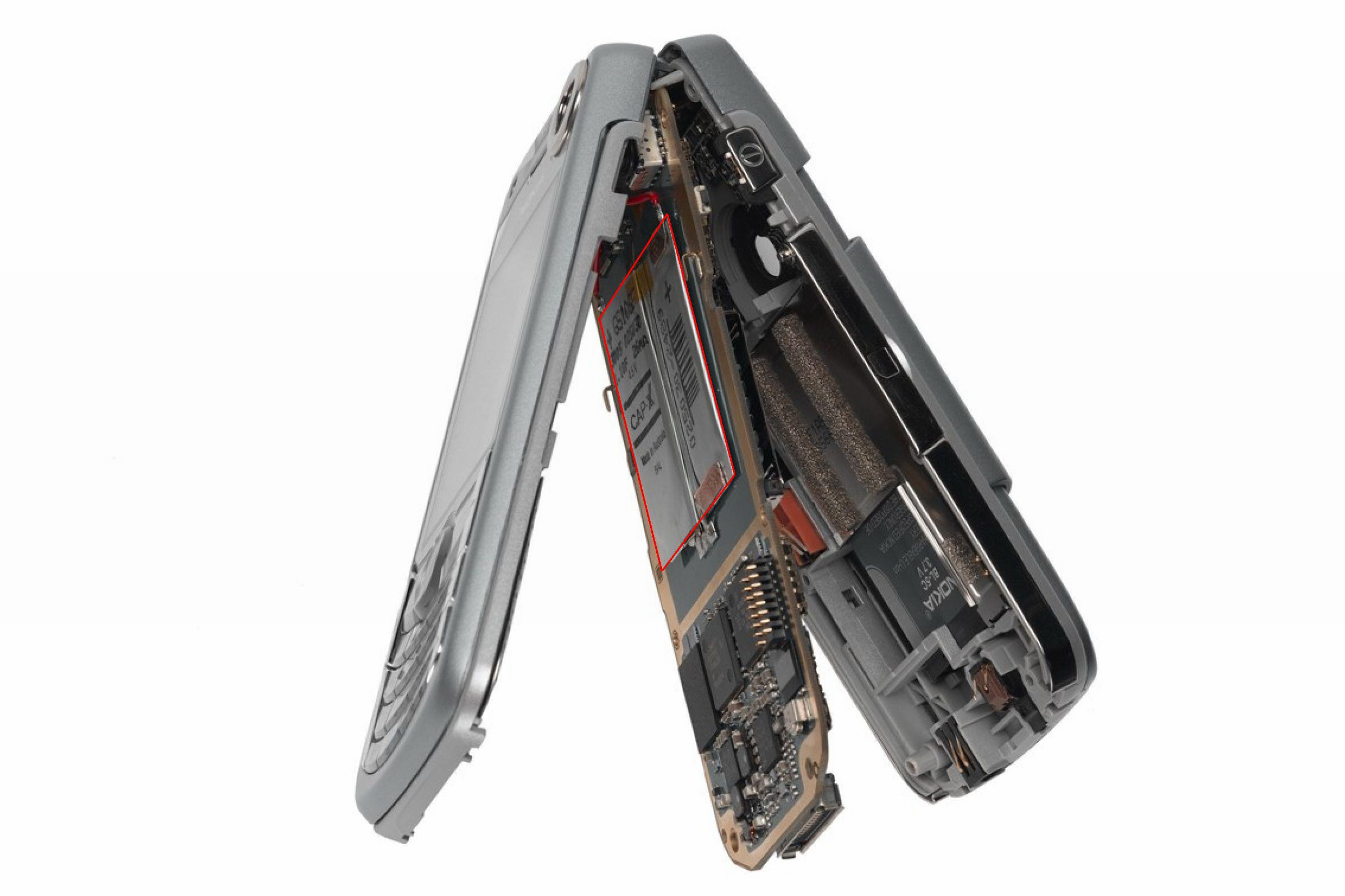
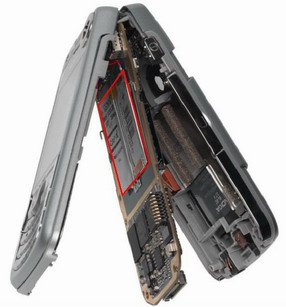
To demonstrate the increased flash power and ease of design-in, CAP-XX engineers retrofitted
several industry-leading camera phones with the BriteFlash™ solution. In this phone, CAP-XX
added a ~1.2mm thick dual-cell supercapacitor [highlighted in red], replaced existing LEDs with 4
high-powered LEDs that can each handle a peak pulse current of 1A, then put the phone together again
with no change in external appearance. The original phone delivered 1 watt of flash power for 160
milliseconds while the CAP-XX-modified phone delivered 15 watts for the same amount of time. |
 |
| High Res JPG Version
High Res TIF Version
|
|
CAP-XX placed two supercapacitor cells and four replacement LEDs in a
leading-brand camera phone to demonstrate its flash power. The photos below were taken using the
unmodified phone on the left and the CAP-XX-modified phone on the right. The unmodified phone
delivered 1W of flash power for 160ms while the modified phone delivered 15W of flash power for 160ms.
|
 |
 |
|
High Res |
High Res |
|
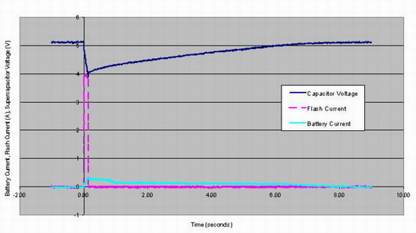
The graph below shows the Battery Current, LED Current, and
Supercapacitor Voltage during a flash pulse and supercapacitor recharge after the pulse. Note that the
Battery Current never exceeds 300mA even though the flash pulse is 4A. The supercapacitor provides
the 3.7A difference. |
 |
|
High Power LED Supercapacitor
Solution Reference Design |
 |
|
High Res |
|
|
BriteSound™ Power Architecture for Music Phones |
Pump up the volume!
Supercapacitors enhance audio quality and power in mobile phones.
As multimedia and music phones grow in popularity, consumers want an iPod-quality audio
experience without the buzzing and distortion associated with wireless transmissions. In the
BriteSound™ power architecture, CAP-XX supercapacitors double audio power for richer-sounding
music and handle peak power demands to eliminate distortion during wireless transmissions.
|
Audio Quality Problems in Music Phones |
Typically, a standard 3.6-volt battery powers two class D amplifiers
to drive a pair of 8-ohm speakers.
For the problems with this typical set-up, see
white paper. |
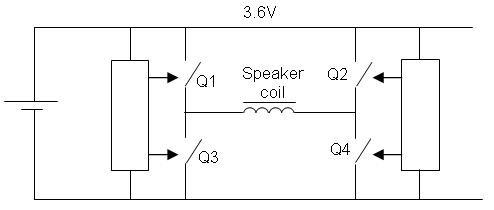 |
| Fig 1: Typical configuration for class D amplifier |
|
| Managing Mobile Phone Audio Power with a Supercapacitor |
In the BriteSound™ power architecture, a 2.4mm-thin,
0.55-farad, 85-milliohm dual-cell CAP-XX HS206 supercapacitor delivers 5W power-bursts to drive
peak-power functions such as audio and LED Flash.
A battery covers the phone's average audio power needs of 0.5 to 1W, recharging the supercapacitor
between bursts. This leaves enough battery power to handle data transfers and network polls without
compromising audio power, eliminating both the distortion and "clicks" normally heard.
The supercapacitor powers the audio amplifier at 5 volts, compared to 3.6 volts directly from a battery,
thereby doubling peak audio power for full-sounding music with a strong bass beat.
The supercapacitor also reduces noise by supplying peak power with less voltage droop than the
battery would, and eliminates any 217Hz buzz when a GSM/GPRS/EDGE phone transmits by protecting
the audio amplifier from other peak loads the battery supplies such as the RF Power Amplifier.
Because the supercapacitor supplies high-peak currents, designers can use higher-quality 4-ohm
instead of standard 8-ohm speakers, further doubling peak audio power. |
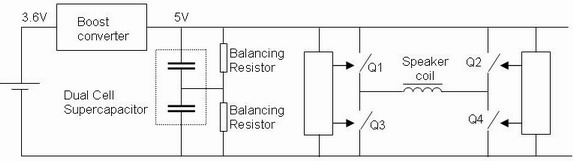 |
| Fig 2: Class D amplifier with supercapacitor |
|
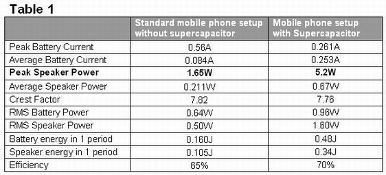
| Tests Comparing Mobile-Phone Audio Quality and Power |
CAP-XX used three cases for comparing audio quality and power,
testing typical mobile-phone audio circuits both with and without a supercapacitor. To test the
difference in power that 4-ohm versus 8-ohm speakers would make, CAP-XX simulated the effect by
attaching a second set of identical 8-ohm speakers in the supercapacitor-powered set-ups.
To test a bass beat and a network poll, CAP-XX built 2 test circuits each with two class D audio
amplifiers, one powered by a battery to drive a pair of 8-ohm speakers, the other supported by a
supercapacitor to drive two pairs of 8-ohm speakers. |
Bass Beat |
CAP-XX used a 100Hz bass beat lasting 120 milliseconds
repeated every 0.5 seconds to test speaker power and battery current. The supercapacitor
tripled peak audio power from 1.65W to 5.2W for fuller-sounding music. Test results are
shown below in Table 1 and Figures 3 and 4. For more technical details,
see
white paper.
|
|
 |
|
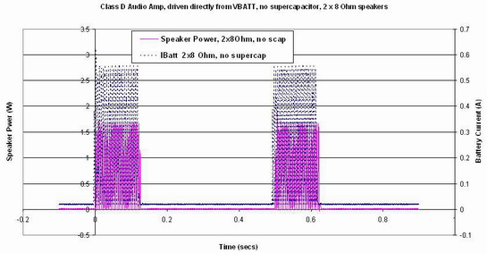 |
| Fig 3: Bass beat, no supercapacitor |
|
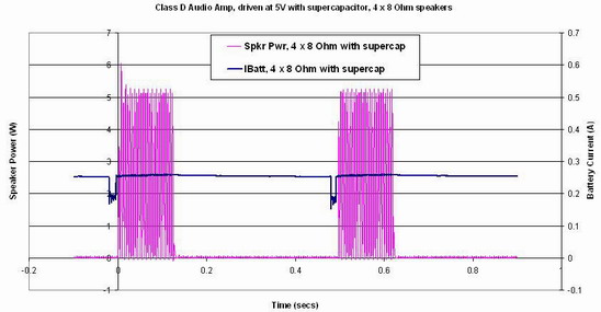 |
| Fig 4: Bass beat with supercapacitor |
|
| Network Poll |
CAP-XX simulated a GSM/GPRS/EDGE network poll while listening to music by applying a
two-amp, 1.15-millisecond power pulse while the audio amplifier was playing a 1KHz tone. The
supercapacitor protected the audio amplifier from the battery voltage droop, eliminating distortion during
wireless transmission. Test results are shown below in Figures 5 and 6. For more technical details,
see
white paper. |
|
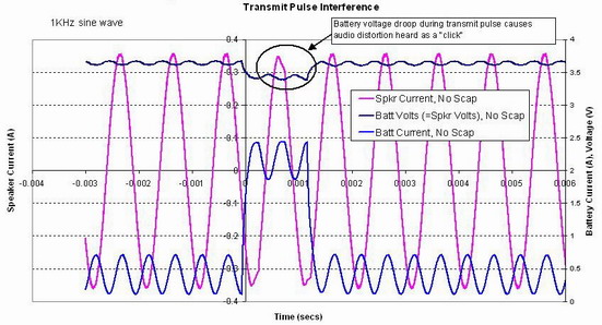 |
| Fig 5: Distortion in audio when battery needs to supply
peak current for audio + RF PA. |
|
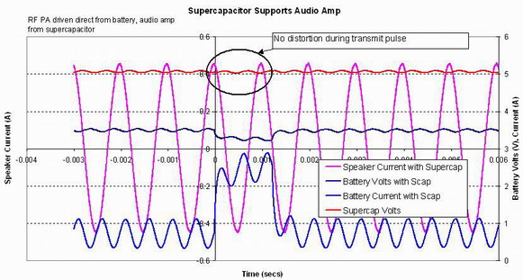 |
| Fig 6: Supercapacitor buffers the audio amp from battery voltage
droop during the RF transmit pulse, so there is no audio distortion |
|
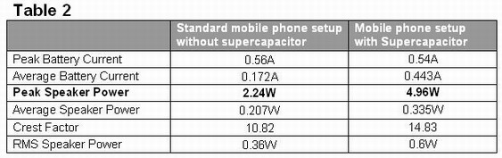
| Listening to a Piece of Music |
CAP-XX used a set of SonyEricsson MPS60 external speakers and audio amplifier as a test
bed. Engineers modified one set with a supercapacitor charged to 5V to power the audio amplifier, then
connected a second pair of 8-ohm speakers to the original pair. Figures 7 and 8 below show the
modifications.
The company played a piece of music to compare the unmodified MPS60 to the
supercapacitor-powered one. The supercapacitor-modified setup more than doubled peak
audio power from 2.24W to 4.96W, so music sounded fuller and richer. Test results are shown
below in Figures 9 and 10 and Table 2. For more technical details, see
white paper. |
|
 |
| Fig 7: External audio amplifier, powered from the phone,
modified to include a supercapacitor |
|
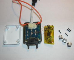 |
Fig 8: Modified external speaker set including a second pair of
speakers
connected in parallel to the original pair. |
Figures 9 & 10 compare battery current and speaker power between the standard set of
speakers and our modified set for a piece of music.
|
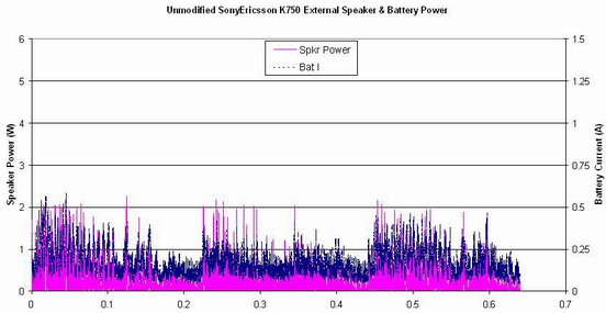 |
Fig 9: Battery current and speaker power while playing music,
standard setup
driving 2 x 8 speakers with audio amp powered from Vbatt. |
|
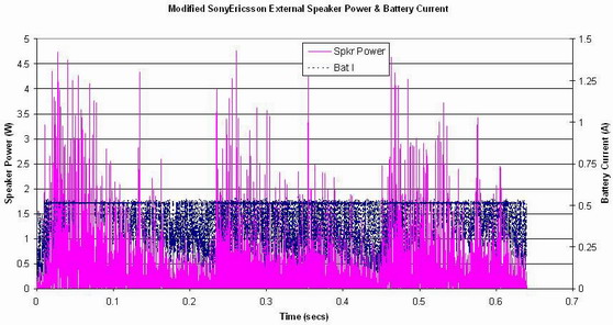 |
Fig 10: Battery current and speaker power while playing music,
modified setup
driving 4 x 8 speakers with audio amp powered from a supercapacitor at 5V.
|
|
 |
|
|
|
|